Wiring
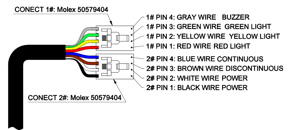
The Light Tower connects via two 4-pin Molex 50579404 connectors.
| Connector | Pin | Wire Color | Function |
|---|---|---|---|
| 1# | 1 | Red | Red light |
| 1# | 2 | Yellow | Yellow light |
| 1# | 3 | Green | Green light |
| 1# | 4 | Gray | Buzzer |
| 2# | 1 | Black | Power |
| 2# | 2 | White | Power |
| 2# | 3 | Brown | Discontinuous (flash mode) |
| 2# | 4 | Blue | Continuous (solid mode) |
important
Only one output on connector 1# — red, yellow, green, or buzzer — can activate at a time.
Mode Control
The Continuous and Discontinuous pins select how the active output behaves:
- Drive the Continuous pin to keep the active color or buzzer solidly on.
- Drive the Discontinuous pin to make the active color or buzzer flash.
Interface Board
The Light Tower plugs into a Studica-designed interface board rather than connecting directly to a controller. The interface board:
- Receives power from the Control Panel V2.
- Accepts digital output signals from a controller, such as the VMX, to select color, buzzer, and mode.
- Contains logic gates that enforce mutual exclusivity between outputs, preventing more than one color or the buzzer from activating at the same time.
tip
Because the interface board's logic gates already enforce this, you don't need to manage mutual exclusivity in your own code — the hardware handles it safely.